PID LoopSim Pro |
| Description and Features: |
Description:
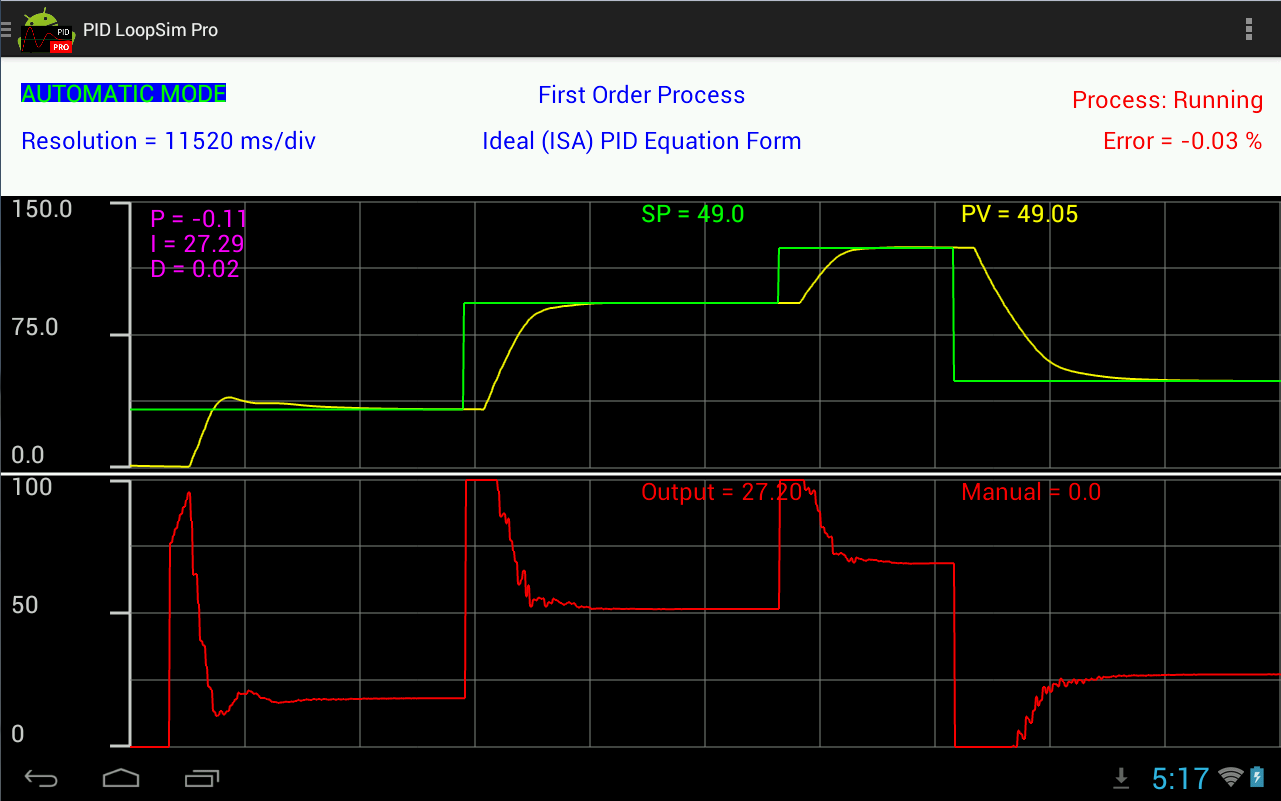
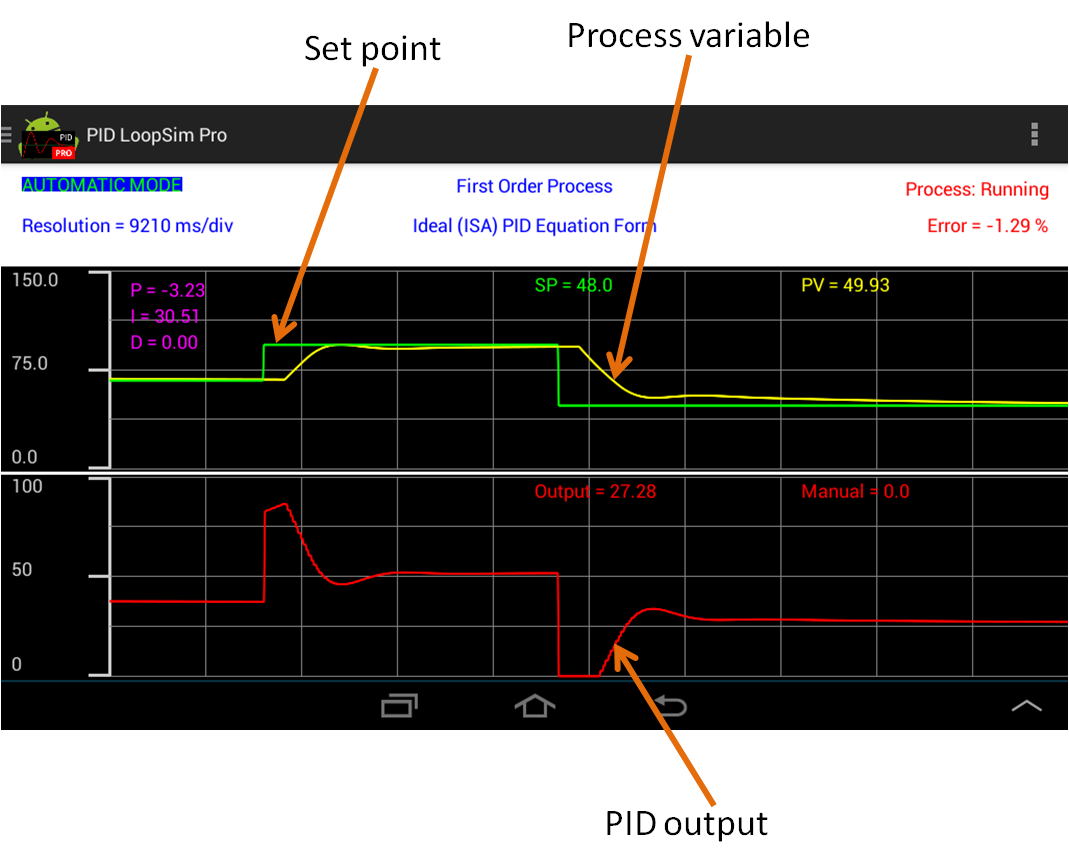
PID LoopSim Pro is an Android-based simulator for PID practice. It may be used to improve tuning skills by adjusting the PID terms in real time and seeing the reaction of the system. Enter your process characteristics and try out the tuning parameters before applying them in your plant. The simulator shows, in real time, how your process will respond to your tuning parameters based on set point changes.
The simulation responds at the same speed that the real plant would do in real life. The purspose of this software is to simulate the response of the process in real-time in order to get a feel of tuning loops in the real plant.
Features:
Manual and Automatic modes
| App Screenshots: |
 |
 |
 |
 |
||
| Free Version vs Full version |
PID LoopSim is the free version of PID LoopSim Pro. It supports most of the features available in the full version, with the following limitations:
| Download and Install: |
 |
|
PID LoopSim Pro |
PID LoopSim |
| User Guide: |
3- Select the type of process and configure the process dynamics
4- Select the PID equation form
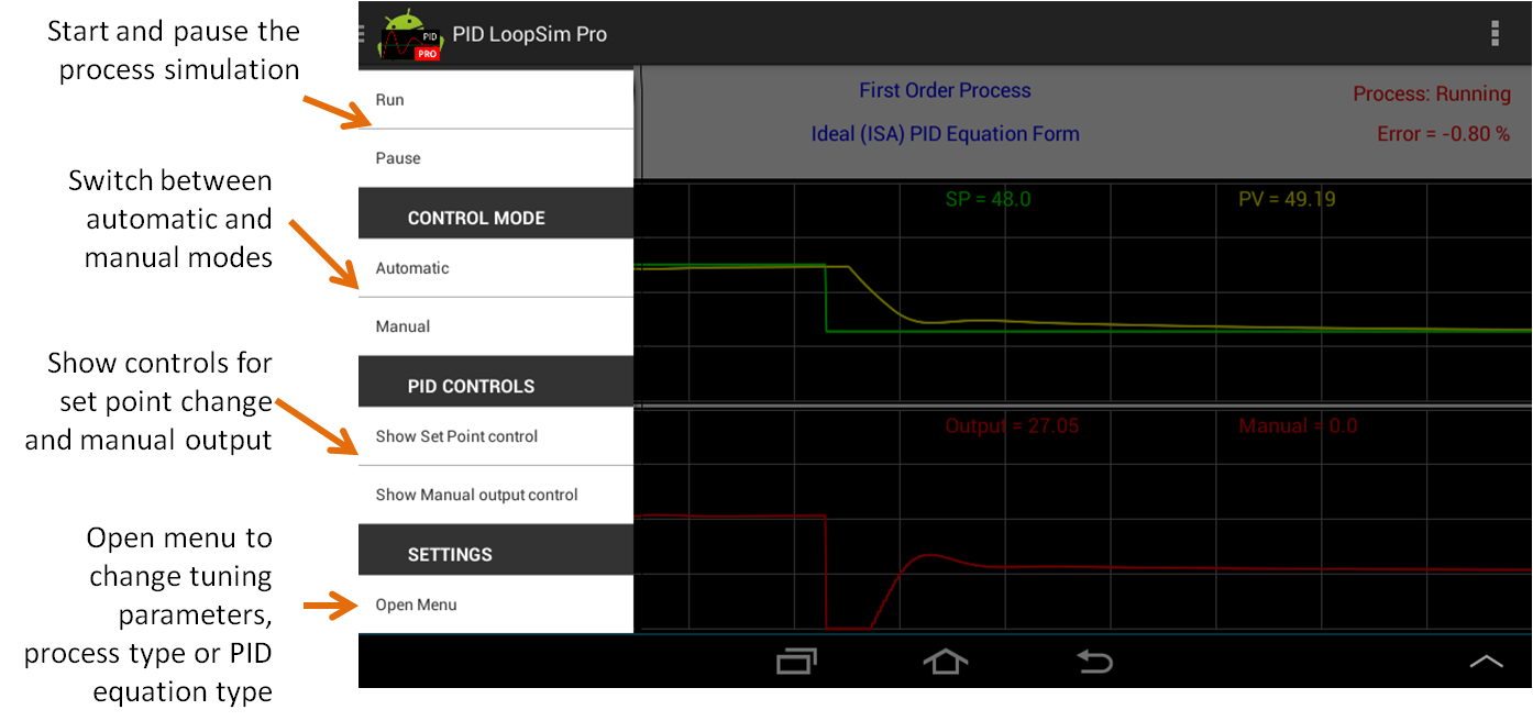
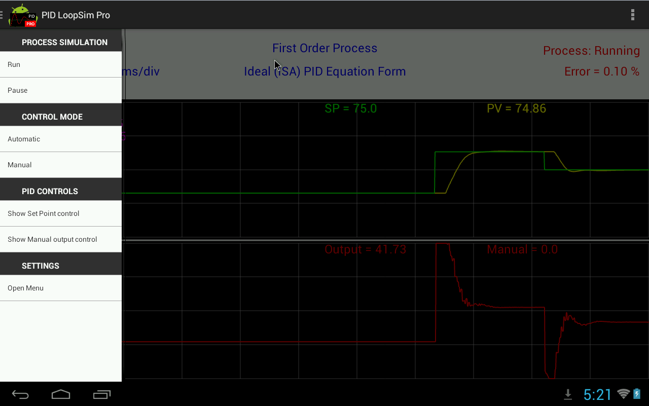
Description of the control options:
Run: Start the process simulation
Pause: Pause the process simulation
Automatic: Switch the process to automatic mode.
Manual: Switch the process to manual mode.
Show Set Point control: Shows the slider to set the set point.
Show Manual output control: Shows the slider to set the PID output in manual mode.
Tuning Constants : Changes the P, I and D constant gains.
System Configuration : Opens the configuration screen to change the PID equation form, the process type and the process dynamics.
Initial setup:
- In the configuration screen, click on Configure Process and select your type of process (1st order, 2nd order or integrating).
- Configure the dynamics of the process (lag time, dead time, etc).
- In the configuration screen, click on Configure PID Controller, then click PID Settings and enter maximum and minimum value of the process variable (in engineering units). This will set the maximum and minimum limits of the trend graphic, and the limits of the set point.
- Configure the PID equation form (ideal form, parallel form, or series form).
Test your process in manual mode:
- In the configuration screen, click on Start Simulation, to go to the simulation screen.
- Switch the control to manual mode by pressing Manual option.
- Open the manual control: click on "Show Manual output control", a slider will pop-up. Touch the slider bar to the desire PID output value (0 to 100%).
- Touch the Run button to start the process. Enter different output values by touching the Manual Control slider, and see the response of the process.
Automatic mode:
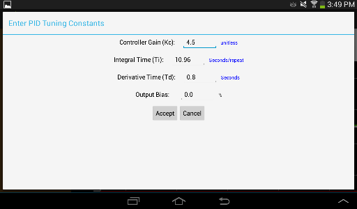
- Open the menu and Tuning Constants. Enter the PID gains. You can change the units of the PID gains by touching them and selecting the new units.
- Touch Accept button to close the PID tuning window.
- Close the Manual Control slider and open the Set Point slider. Touch the Set Point slider to enter a new set point value. In the trend graphic, the green line will show the new set point.
- Touch "Automatic" to switch the control to automatic mode.
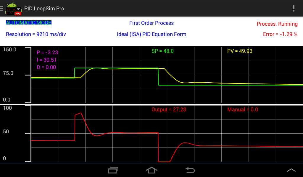
- See the response of the process variable (yellow line). Make set point changes by touching the set point slider and see the response of the process.
3- Select the type of process and configure the process dynamics
PID LoopSim allows you to simulate three different type of processes:
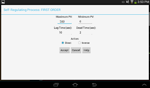
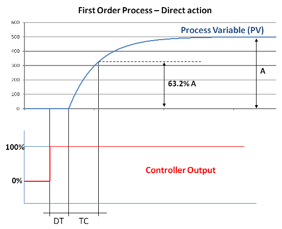
A- First Regulating Process - 1st order:
Maximum PV: Steady state value of the process variable (in engineering units) when the PID controller output is 100%.
Minimum PV: Steady state value of the process variable (in engineering units) when the PID controller output is 0%.
Lag Time (TC) : Time constant of the process. 63.2% of process step response (see graphic below).
Dead Time (DT): Process delay (see graphic below).
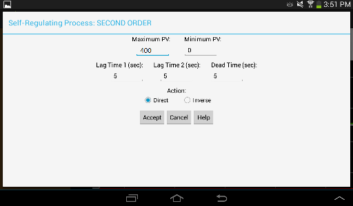
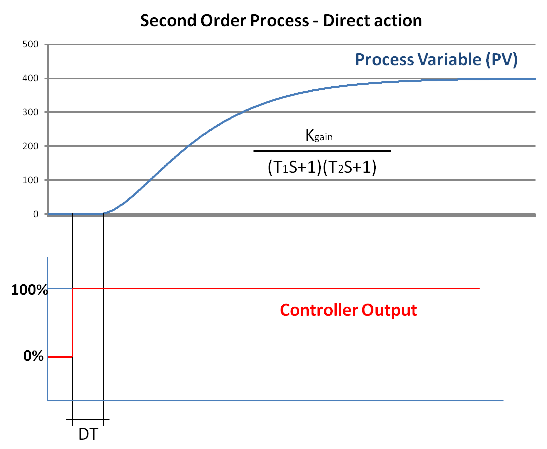
B- First Regulating Process - 2nd order:
Maximum PV: Steady state value of the process variable (in engineering units) when the PID controller output is 100%.
Minimum PV: Steady state value of the process variable (in engineering units) when the PID controller output is 0%.
Lag Time 1 / Lag Time 2 (T1 and T2) : Time constants of the process (see graphic below).
Dead Time (DT): Process delay (see graphic below).
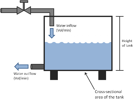
C- Integrating Process (tank level control):
Max Inflow Rate : Water flow rate (units: volume/minute) when the valve is 100% open.
Output Flow Rate : Flow rate of the water leaving the tank (see graphic below).
Dead Time (DT): Process delay (see graphic below).

4- Select the PID equation form
PID LoopSim supports three forms of the PID equation:
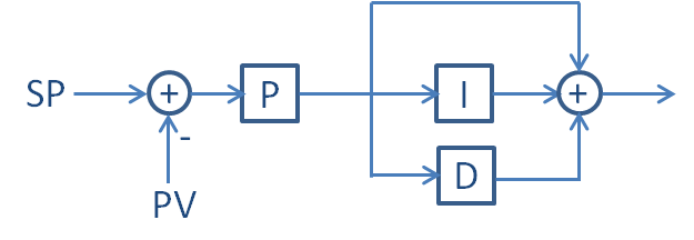
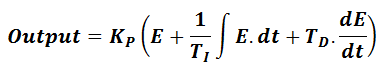
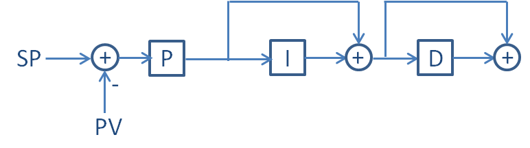
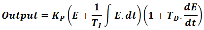
A- Ideal PID equation:
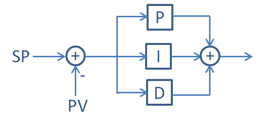
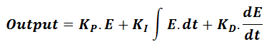
B- Parallel PID equation:
C- Series PID equation:
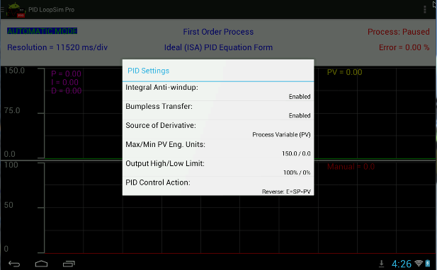
Integral Anti-Windup: When enabled, the integral calculation suspends if the calculated output is outside the output high/low limits.
Bumpless Transfer: Enables output tracking and set point tracking, when in manual mode, to allow a smooth transfer from manual to automatic.
Source of Derivative: Select between derivative on error or derivative on process variable.
Max/Min PV Eng. Units : Maximum and minimum process variable engineering units for PID calculation. This values are used internally in the PID logic to calculate the error in percentage.
Output High/Low Limits : Maximum and minimum value of the output.
PID Control Action : Direct Control Action (Error = PV - SP) or Reverse Control Action (Error = SP - PV). Control action must be set to the opposite of the process action. E.g. for direct acting processes, use reverse control action.
PID execution rate can be configured between 0.1 sec and 10 sec.
To change the PID execution rate go to Menu -> PID Controller -> PID rate